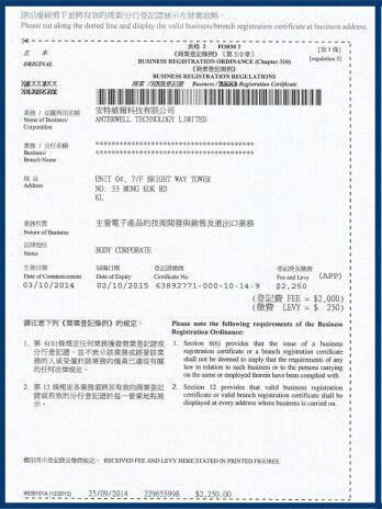
Anterwell Technology Ltd.
Anterwell Technology Ltd.
Large Original stock of IC Electronics Components, Transistors, Diodes etc.
High Quality, Reasonable Price, Fast Delivery.
Anterwell Technology Ltd.
Large Original stock of IC Electronics Components, Transistors, Diodes etc.
High Quality, Reasonable Price, Fast Delivery.

Product Details:
Payment & Shipping Terms:
|
| Payment: | T/T, Western Union, Paypal | Main Line: | IC Components, Transistor, Diode, Module,Capacitor Etc |
|---|---|---|---|
| Temperature: | –40 To +105°C | Current: | 16V |
| Factory Pack: | 1000pcs/reel | Package: | SMD6.3*7.7 |
| High Light: | ferrite bead model,multilayer ceramic chip capacitors |
||
Capacitor 220uF 16V ECEV1CA221XP
Aluminum Electrolytic Capacitor/V-G
Features Endurance :105°C 1000 h
■Specification
| Operating temp. range | -40 to + 105°C |
| Rated W.V. range | 6.3 to 50 V .DC |
| Nominal cap. range | 0.1 to 470 µ F |
| Capacitance tol. | ±20 % (120Hz/+20°C) |
| DC leakage current | I < 0.01 CV or 3 (µ A) after 2 minutes |
Explanation of Part Number
E C E V [] [] G [] [] [] []
Common code Shape W.V. code Series code Capacitance code Suffix
1. Circuit Design Ensure that operational and mounting conditions follw the specified conditions detailed in the catalog and specification sheets. 1.1 Operating Temperature and Frequency Electrolytic capacitor electrical parameters are normally specified at 20°C temperature and 120Hz frequency. These parameters vary with changes in temperature and fr equency. Circuit designers should take these changes into consideration. (1) Effects of operating temperature on electrical parameters a)At higher temperatures, leakage current and capacitance increase while equivalent series resistance(ESR) decreases. b)At lower temperatures, leakage current and capacitance decrease while equivalent series resistance(ESR) increases. (2) Effects of frequency on electrical parameters a)At higher frequencies , capacitance and impedance decrease while tan δ increases. b)At lower frequencies, ripple current generated heat will rise due to an increase in equivalent series resistance (ESR).
1.2 Operating Temperature and Life Expectancy (1) Expected life is affected by operating temperature. Generally, each 10°C reduction in temperature will double the expected life. Use capacitors at the lowest possible tem perature below the maximum guaranteed temperature. (2) If operating conditions exceed the maximum guaranteed limit, rapid eIectrical parameter deterioration will occur, and irreversible damage will result. Check for maximum capacitor operating tempera- tures including ambient temperature, internal capacitor temperature rise caused by ripple current, and the effects of radiated heat from power transistors, IC?s or resistors. Avoid placing components which could conduct heat to the capacitor from the back side of the circuit board. (3)The formula for calculating expected Iife at lower operating temperatures is as fllows; L2 = L1 x 2 where, L1: Guaranteed life (h) at temperature, T1° C L2: Expected life (h) at temperature,T2°C T1: Maximum operating temperature (°C) T2: Actual operating temperature, ambient temperature + temperature rise due to ripple currentheating(°C) A quick eference capacitor guide for estimating exected life is included for your reference
High Power Rectifier Diode 1N4756A , Silicon Planar Zener Diodes
Bridge Type Rectifier Diode 1N4007 50 to 1000 Volts 1.0 Ampere
1N4742A Silicon Planar Zener Diodes for Stabilized Power Supply
Power Programmable IC Chips XC6SLX100-3FGG484C Spartan-6 Family Overview
128K Bytes Sound IC Chip Programming ATMEGA128-16AU 8 Bit Microcontroller
EMC Programmable IC Chips Compliant Slew Rate Limited EI , Timer IC Chip
SMD Power Mosfet Module L7812CV TO-220 Power Trans Electronic Compoents
2SD1594 3 Pin Transistor NEC NPN Power Transistor Switching High Speed
2N5459 Power Mosfet Transistor N-Channel To-92 Original Stock FSC
